Air-Care Logo Blue Long

TURBOMAX 3

TM-3-Manual-Cover-Image-WEB

*All specifications and prices are subject to change and improvement without notice.

Unpacking

Check that all parts are present

TurboMax 3 Main Assembly, with Wheels, Motor and Blower. Release the 4 side latches and lift the front of the upper section so it hinges up to check for filters. The HEPA filter will remain in the bottom section, the First Stage, 1” pre-filter frame and pad will remain in the top section and the Flexible electrostatic 2nd stage filter will be mounted in the top of HEPA frame.
• First stage, 18” x 24” x 1” Electrostatic with disposable pads
• Second stage, 18” x 24” x FLEX Electrostatic Air Filter
• Third stage, 18” x 24” x 4.75” Certified HEPA Filter
• 25’ Power Cord.
• The handle is wrapped separately and shipped loose in the box.
• The 12” Dia. Hose adapter Plate is over the Inlet.

Remove the outer box and inspect for damage. Report all damage immediately to your carrier. If special set-up instructions are required, they will be taped to the outside of the Equipment or in the “Operating” section of this manual. Inspect all of the packing material for small parts before discarding packaging material. Report all damage to Air-Care immediately. Any attempt at repairing damages may void warranty.

Safety

Always use safe and common sense precautions when working with Air-Care equipment. Do not block walkways with equipment, and remove delicate and breakable articles from the immediate work area. The following are precautions that should be reviewed by all persons who will be involved in the cleaning activity:

• Other than the 3 filters, there are no user serviceable components in Air-Care’s TurboMax 3. Only trained technicians should attempt to make internal repairs on this equipment.

• Always turn off the main power switches on the TurboMax 3 front Panel, or disconnect the power before opening or removing the doors or filters.

• Inspect AC power plug to be sure the ground pin is in place. DO NOT USE AN EXTENSION CORD. Plug power cords directly into 2 independent power outlets.

• Never connect power to Air-Care equipment unless all covers and safety shields are in place. Mechanical and electrical parts could activate and cause injury.

• Never allow anyone but a properly trained technician to use the equipment or cleaning products.

• All Air-Care equipment is designed for US standard 115 volt, 60 Hz AC. Most Air-Care equipment can be special ordered to meet other worldwide standards for a reasonable price and delivery schedule. Always check the specifications on the equipment before connecting electrical power to Air-Care equipment.

Handle Installation

handle_Photo

Handle is wrapped and packed near the bottom, front of TurboMax 3.

It must be installed with the 4 bolts provided and your ½” socket wrench or nut driver.

Set-up/Testing

Air-Care TurboMax Negative air machines are designed to “Pull” loose debris out of the air system to which they are connected and filter out harmful debris such as pollen, dust, mold spores and other debris with their 3 stage HEPA filter system. An agitating device to “Push” debris is required to properly clean an air system. The Cobra Power Brush System or the Air Whisk and Sidewinder air tools are designed to loosen and agitate debris so the TurboJet can pull it out. See the “Duct Cleaning” section on page 8 of this manual for a summary of proper duct cleaning procedures.

To test the TurboMax 3, be sure all filters are in place and the Top is closed and latched in place.

1. Set the “Run” switch is in “STOP” Position.

2. TURN OFF the Circuit Breakers.

3. Connect the 12 gauge x 25-foot power cord, with GROUND Pin, to 20 AMP outlet that DOES NOT have other devices plugged into them. (220 Volt Version has one twist lock cord and one dual circuit breaker/power switch).

4. AFTER the power cord or power cords are connected, Turn on the circuit breaker switch.

Status Lights

Red/Green Status LED. The TurboMax 3 will operate with GNA 20 AMP, 120 volt AC power Cord connected to dedicated circuit rated at 20 Amps.

Duct Cleaning Procedures

Effective duct cleaning can be accomplished with the TurboMax 3 connected to one of the following positions in the duct system. The “best” location is determined by the specific configuration of the particular air system.

A. With a basement or crawlspace air conditioner/furnace

Cutting an access hole in the side of the supply side main trunk line is very effective. Be sure that no airflows through the furnace a/c coils. To stop air from coming through the furnace, block the return openings with cardboard and duct tape. An alternate way to block the airflow would be to slip the customers existing furnace filter in a plastic trash bag and reinstall. If there are returns in each room, you will also need to connect to the return trunk line at the furnace and block it off while cleaning the return ducts. If you need advice on how to connect to an unusual system, call Air-Care for assistance

B. With a garage, interior closet or roof mounted up-flow air conditioner/furnace

Just remove the diffuser grill from a large ceiling or wall mounted supply duct and use the Pogo Pole hose adapter to connect the TurboMax 3 inlet hose to the system. Connecting to a large supply duct is very effective. Gravity will help “pull” dust and debris into the Turbojet.

In some cases, it may be best to attach the TurboMax 3 to each Supply or return duct and insert the agitation device into that same duct opening to disturb debris as far up stream and down stream as possible.

To obtain maximum “pull”, always keep the attaching hose as short and as straight as possible.

1. Bring the TurboMax 3 into close proximity to the planned connection ducts.

2. Connect the 12 gauge, grounded, electrical power cords to an independent electrical outlet (110V, 20 AMP). It is recommended to NOT use longer or smaller gauge extension cords. A good ground connection in the power cord is a SAFETY Feature.

3. Connect a 12” hose to the 12” TurboMax 3 inlet. To obtain maximum “pull”, always keep the attaching hose as short and as straight as possible.

4. Connect the other end to the most effective supply duct location using the optional Pogo Pole hose adapter or 12” adapter plate.

5. Close off the return side of air handler by putting a filter in a plastic bag and reinstalling it into its holder.

6. Turn on BOTH Circuit Breaker switches (within 2 seconds of each other) at the bottom of the panel then Select “Power Level “1” if using one Power Cord, or Power Level “3” if using 2 power cords. Power Levels “2” and “4” can be used if the Circuits are rated for 20 Amps.

7. Use the RUN switch to start the TurboMax 3 motor.

9. After all ducts are cleaned, the ducts can be fogged with an EPA-registered deodorizer or Air-Care’s Filter Deodorizer.

10. Before fogging the supplies, turn off the power switch.

11. Remove hose from the top of the TurboJet.

12. Place a piece of pellon, 20” X 22” over the 12” inlet.

13. Re-install the hose, and turn on the power switch.

14. Fog the supplies, beginning with the most distant supply.

15. When the fogging is complete, turn off the power; remove the hose from the TurboJet and the supply duct.

16. Remove and discard pellon.

17. Inspect first stage filter, if loaded with debris, take the TurboJet out of the building and dump it out or replace as required.

18. Inspect electrostatic flex filter and wash if soiled.

19. Unplug power cords, put TurboMax 3 back into the vehicle, and complete the job.

Troubleshooting

SymptomCheckCorrective Action
Motor does not start when RUN switch turned on.Is Panel Status Light On and GREEN?If Yes: Check connections to motor, control panel. Call Air Care.

If No: Check and reset circuit breakers and verify electrical outlets have power. Turn OFF for 3 min, then turn Turn ON Breaker
No vacuum with motor running.Is blower turning?If Yes: Motor May be running in Reverse, contact Air-Care

If No: Tighten shaft adapter bolts and align wheel & inlet cone. (Call Air-Care)
Is the “Change HEPA” light on?Are the 1st stage pre-filter and 2nd stage Electrostatic filters clean?If Yes: Replace HEPA filters as required.

If No: Clean 1st and 2nd stage air filters.
Insufficient “pull” at duct.Is the “Change HEPA” light on?If Yes: Replace HEPA filter as required.

If No: Check for disconnected, collapsed or broken system ducts.
d to it.

If No: Inspect 12” hose for cracks or holes.
Circuit breaker trips when TurboMax is turned on.Is the TurboMax 3 connected to 2 SEPARATE dedicated 115-volt, 20-amp line.If Yes: Be sure TurboMax 3 is connected directly to the power outlet. DO NOT use an additional extension cord.

If Yes: Be sure that only the original 12 gauge (or heavier) 25 ft. power cord is used on the TurboMax 3.

If No: Call Air-Care

If No: Find another outlet on circuit that does not have other devices connected to it.

Maintenance

NOTE: Never wash the HEPA filter with water.

The TurboMax 3 requires a minimum amount of maintenance, normally limited to cleaning or replacing filters as they become filled with dirt and debris. Cleaning the 1st and 2nd stage filters daily will extend the life of the 3rd stage HEPA filter.

1st and 2nd Stage Filter Replacement

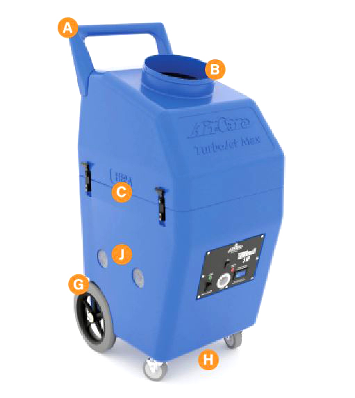
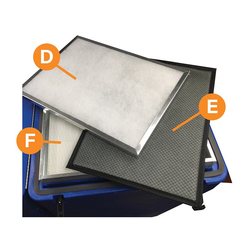
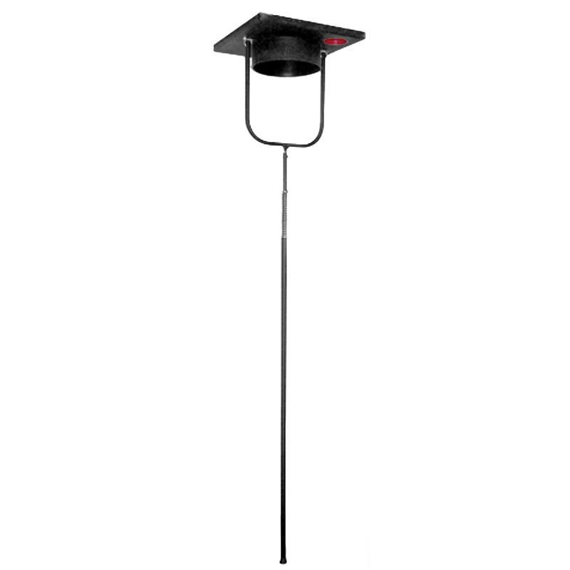
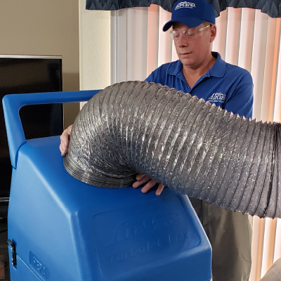
1. The 1st stage 1” electrostatic filter with disposeable pads is mounted in the top section of the TurboMax 3 and held in place with a metal bracket at one end and a Velcro strip in the center of the other end. It is disposable, but it may be possible to dump out large debris and use it 2 or 3 times if it is not torn or damaged. The duct debris captured in the upper section and first stage filter can be collected in a trash bag placed over the 12” Hose inlet and secured with the Velcro strap. Unlatch the top section and tip it back on its hinge so the debris falls into the bag from the upper section of the TurboMax 3 and its first stage filter. Follow all local regulations on disposing of material removed from the ducts. In critical areas, such as hospitals, it is required to cover the inlet with 6-mil plastic when the job is completed to prevent the collected debris from escaping and contaminating the area while it is removed from the building to be emptied in a non-critical area where the trash bag can be disposed of safely. The first stage filter can be put into the same trash bag for disposal.

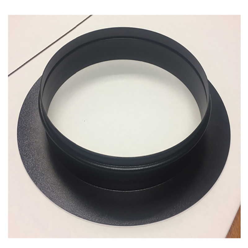
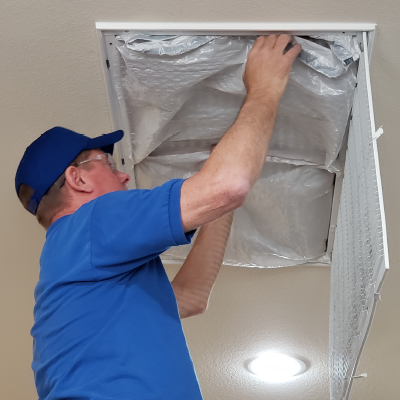
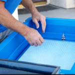
2. The 2nd stage “Flexible” permanent electrostatic filter is mounted in the top of the HEPA filter frame. When necessary, wash the 2nd stage filter with a garden hose and nozzle at full force. First rinse in the opposite direction of the airflow, then rinse both sides. Occasionally, a degreaser such as Air-Care C.E.F. (Cleans Electrostatic Filters) electrostatic filter cleaner may be required to restore this filter to its’ peak performance. Let the filter air dry before reinstalling into the unit.

Note: When there is not sufficient time to allow filters to dry before using the TurboJet, simply dry vacuum the loose debris off of the filters’ surfaces or use compressed air in an appropriate outdoor area.

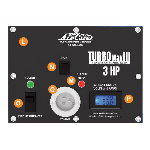
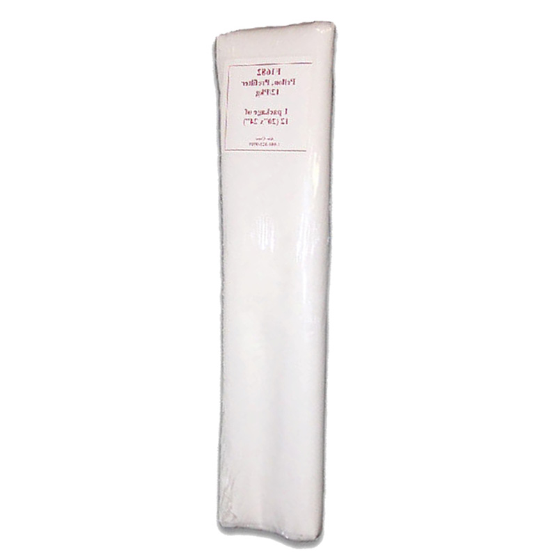
When the control panel “Change HEPA” red LED is on and the 1st and 2nd stage filters are clean, the 3rd stage HEPA filter should be replaced (approximately once or twice per year, if other filters are cleaned regularly). There is no safe way to clean the HEPA filter without a risk of damaging it.

HEPA Replacement

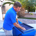
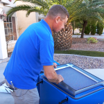
1. Open the upper section of the TurboMax 3 to gain access to the filters. The first stage filter will be held in the upper section of the TurboMax 3.

2. The second stage filter must be removed from the HEPA frame.

3. Use care when removing the 3rd stage HEPA filter mounted in the bottom half of the cabinet. When the airflow through the inlet is noticeably reduced and the 1st & 2nd stage filters are clean, it is time to replace the 3rd stage HEPA filter.

NOTE: Applying compressed air pressure or using a vacuum brush on HEPA filter surface will damage the filter. If you have any questions, please call Air-Care at 800-322-9919

Parts and Accessories

You can order the part by clicking the part number. You will be directed to the item page on Air-Care.com
DescriptionPart #
TurboMax 3, 120 Volt Model.FG0282
First stage, 18” x 24” x 1” Electrostatic Filter with Pads (5 Replacement Pads SAO0574)FG0259
Second stage, 18×24 Flex 94%F0017
Third stage, 18” x 24” x 4.75” HEPA FilterFOO59
25’ Extension Power CordEC0005
Pogo Pole Hose Adapter 12” (Optional)FG0038
Cap Plug, 4” Red (for Pogo Pole Assembly) (Optional)COM0239
12” x 12.5’ Heavy Duty Hose with Velcro StrapsFG0056
12” x 25’ Light Duty Mylar Hose with Velcro Straps (Optional)FG0003
Foam Register Plugs, 14pc./pkg. (Optional)FG0050
Pre-Filter, Pellon Moisture Barrier Sheets, 12/pkg. (Optional)SAO0079
12” Adapter CollarFG0041
Air-Care Fogger Model 2600 120 Volt(for 220 Volt Call) (Optional)FG0186
Cobra VI, Power Brush System (Optional)FG0194
Forward and Reverse Air Whisk System (Optional)FG0015
Sidewinder Hose Assembly (Optional)FG0030
HEPA Back Pack Vacuum 120 Volt (for 220 V Call) (Optional)FG0069

A. Molded Handle

B. 12” Dia. Hose Inlet

C. Locking Latches

D. First stage, 18” x 24” x 1” Electrostatic Filter with Pads

E. 2nd Stage 18” x 24”Flex 94% Electrostatic Air Filter

F. 3rd Stage 18” x 24” x 4.75” HEPA Filter

G. 12” Non-Marking Wheels

H. Front Swivel Casters

I. Power Cord

J. Exhaust Grills

L. SuperMax Control Panel Assembly

M. Change HEPA light

N. Switch, DPST “RUN”

O. Circuit Breakers/Power Switch, Dual 20 amp.


O. Power Switch, 1 & 2 for 1 Power Cord 3 & 4 for 2 Power Cords

P.Circuit Status Indicator

Q. Power Receptacle

Optional Parts and Accessories

12” Pogo Pole Hose Adapter (Complete Assembly comes with Pole, Fork, 20 X 20 X 2 Foam attached to 12” Steel Pogo Plate & 4” Red Cap Plug) (FG0040)

12” Adapter Plate (FG0041)

12” x 12”, 26 gauge, Galvanized Steel Duct Patches

Pre-Filter, Pellon Moisture Barrier Sheets (12/pkg) 

Foam Register Plugs (14/pkg)

Sidewinder Hose Assembly

12” x 12.5” Light Duty Mylar Hose with Velcro Straps

Forward and Reverse Air Whisk System

HEPA Back Pack Vacuum

Air Care Single Fogger (FG0186)

Cobra Power Brush System (FG0194)

Specifications

SpecificationDescription
Size19.5” W x 29” D x 55 ½” H
Weight151 lbs.
Power required120 V, 60 Hz, 13 to 17 amps.
Power Cord25’ Extension Cord, 12 gauge
Filtration4 stages when Pellon pre-filter used
Pre-FilterPellon Moisture Barrier
1st Stage18” x 24” x 1” Disposable Polyester Filter Pad + 1” Frame
2nd Stage18” x 24” Flexible Electrostatic Air Filter
3rd Stage18” x 24” x 4.71” Certified HEPA Filter
Attachment12” Dia. Inlet
Operating Environment25 to 125 Deg. F (-4 to 50 Deg. C)
ConstructionRotation Molded Poly with Internal Steel Reinforcement
Operating ControlsPlug-able Panel with Multiple Speed control, Dual Ammeters, Change HEPA Light, & Circuit Breakers
Air Flow3500 CFM with all Filters in place
Static Pressure6.3” W.G.
Motor3 HP , Inverter Rated, 3 Phase Motor, 3600 RPM Maximum
Variable Speed, Dual Voltage Motor InverterInput 120 VAC, 50/60 Hz, 15 or 20 Amp each One or Two separate household circuits. (Optional: 1- 220V, 7, 10, 13 or 18 amp )
BlowerOne – Backward Inclined
WheelsTwo – 12” Fixed Rear and Two – 4” Front Swivel Non-Marking Locking Wheels

*All specifications and prices are subject to change and improvement without notice.

Limited Warranty

TURBOMAX 3

Air-Care warrants this product to be free from defects in materials and workmanship to the original purchaser for a period of Three (3) years from the date of purchase. Components listed below are excluded from this Three year period and are covered for periods described below:

Vacuum Motors: 1 Year
Power Inverter: 1 Year
Wheels & Filters: No Warranty

Warranty covers both parts and labor (labor is to be performed at Air-Care’s facility located at 3868 E. Post Road; Las Vegas, Nevada).

Warranty is extended to the original purchaser and is not transferrable.

This warranty does not extend to any damage to a product caused by or attributable to freight damage, abuse, misuse, improper or abnormal usage. Warranty is also void if the product has been modified or altered in any way.

The purchaser is responsible for the cost of shipping the equipment to Air-Care’s facility for evaluation. If found to be defective and covered by the terms of this warranty, Air-Care will pay FedEx ground shipping charges on the repaired or replaced item back to the purchaser’s location. Any additional expedited service charges for quicker shipping shall be born by the purchaser. If the product or component is not found to be a warranty issue, the purchaser will be responsible for return shipping charges.

Air-Care is not responsible or liable for indirect, special, or consequential damages arising out of or in connection with the use of performance of the product; damages with respect to any economic loss, loss of property, loss of revenues or profits, loss of use, or other incidental or consequential damages of whatsoever nature.

The warranty extended hereunder is in lieu of any and all other warranties, and any implied warranties of any type.

This warranty gives you specific rights. These rights and others vary from state to state.

Division of D.P.L. Enterprises Inc.
3868 East Post Road, Las Vegas, Nevada 89120, (702) 454-5515, FAX (702) 454-5225
Website: www.air-care.com • E-mail: Info@Air-Care.com